Construction of the main rotary mount
construction report rotary mount
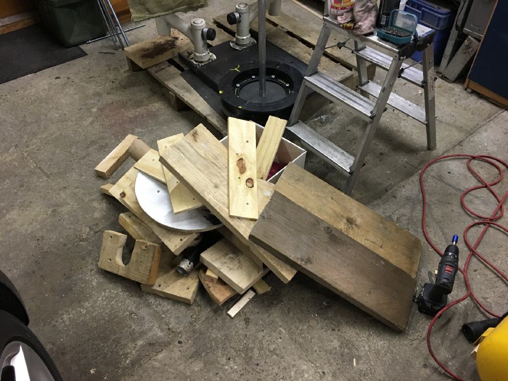
I have found that when building a 1: 1 model, you can pre-model some parts very well and simply with wood and then get the final dimensions for the steel parts.
That's what I did with the rotary mount.
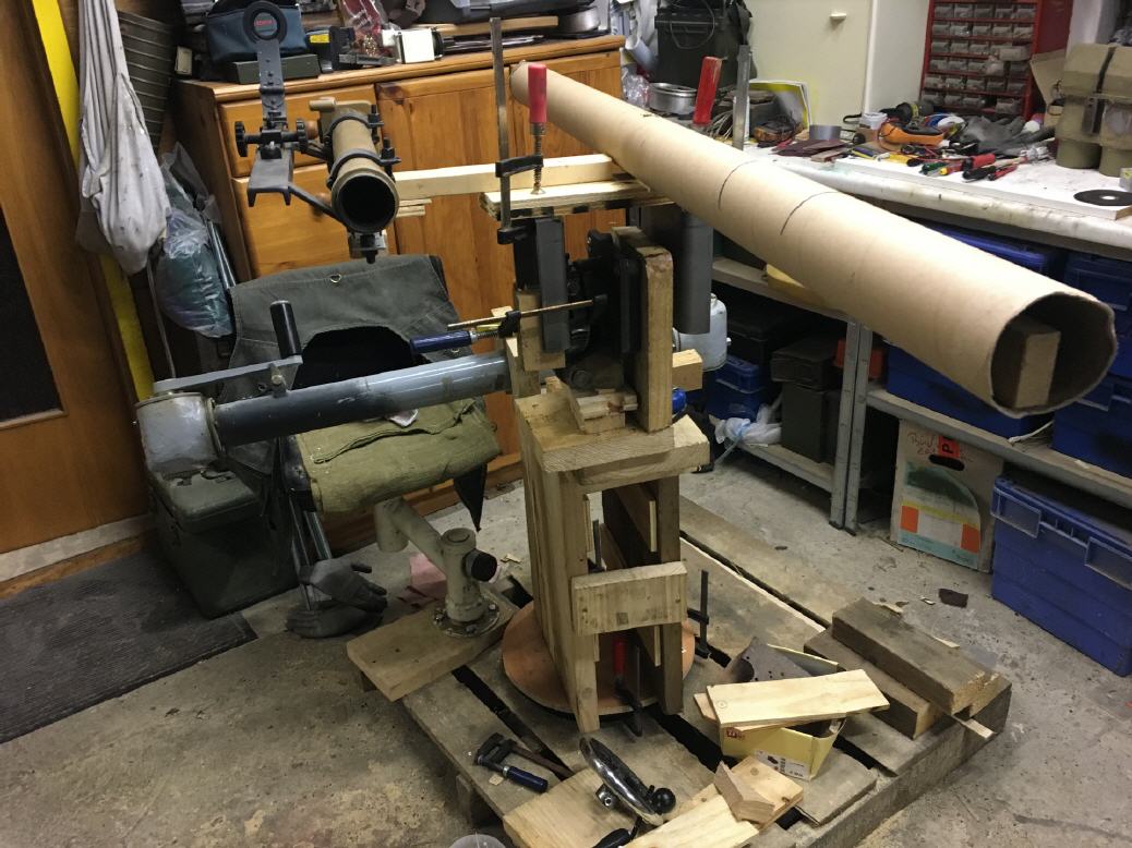
I used a worm gear made from an old tilting frying pan of a canteen kitchen for the lift / lowering unit for the weapons / riflescope unit.
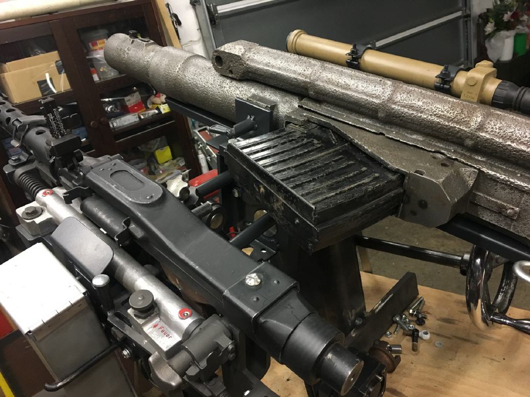
The MG 34 is a complete replica. The 2cm-Flak is a completely cleared original part.
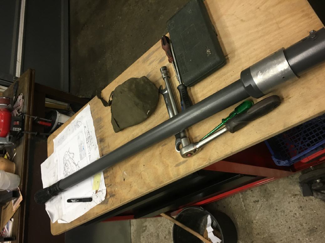
I rebuilt the barrel completely from aluminum according to original specifications. Only the muzzle brake is original.
The lock for the barrel in the housing works, I found these parts in the internet.
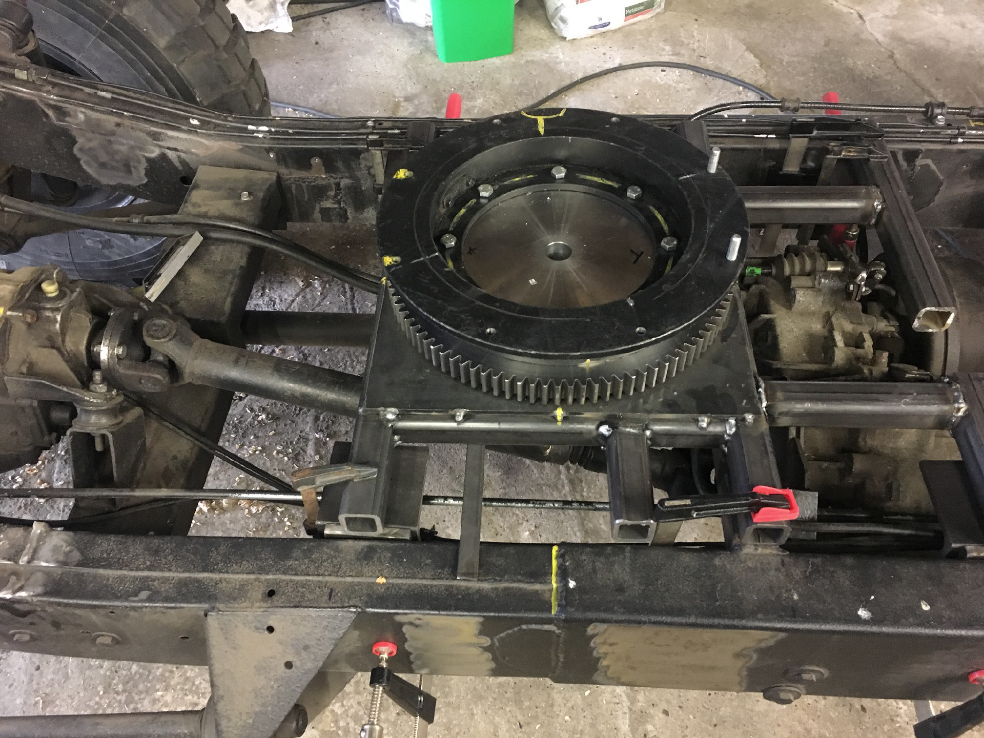
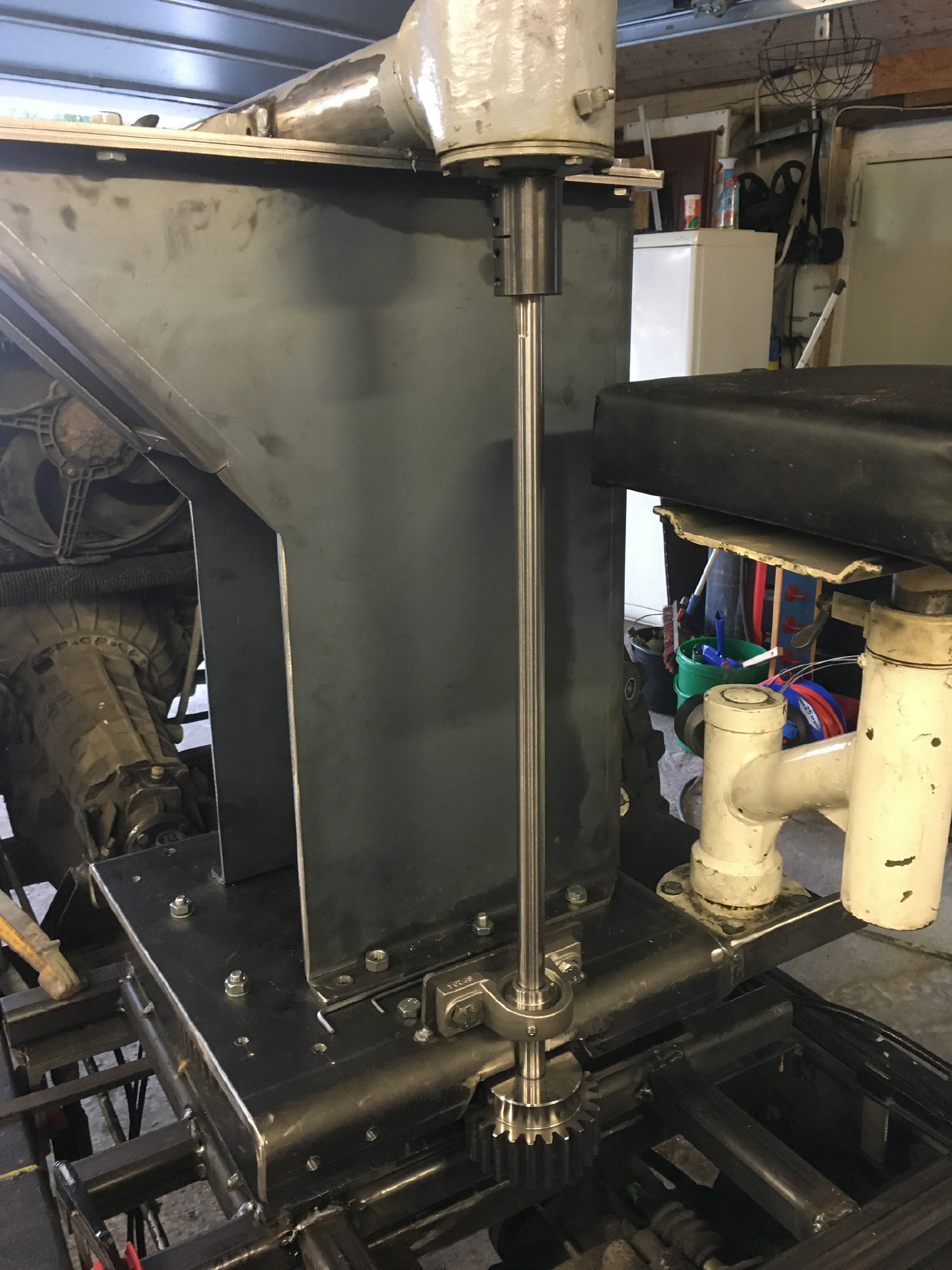
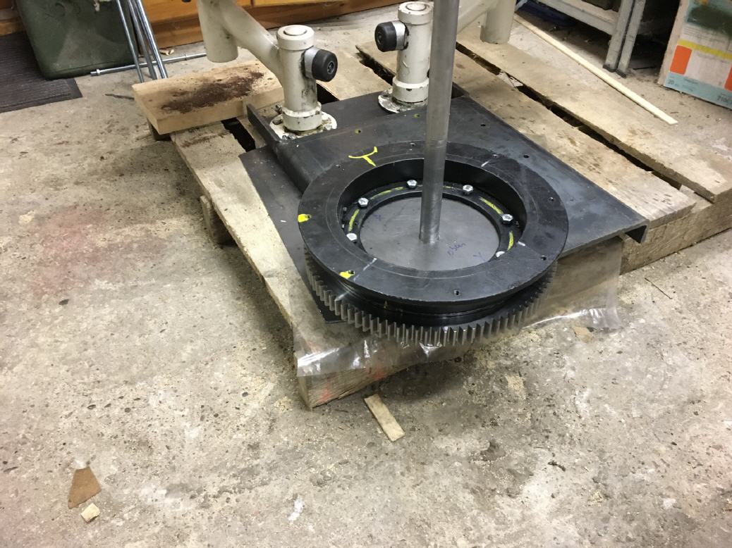
The base plate is screwed on a slewing ring, which lower part is attached to a Modul4-gear. The entire unit is then turned around the gear via a angular gear.
and that's left over from the wood experimental setup ...
since I can also heat with wood, all this has found a meaningful use.
Update April 2019
Update April 29, 2019
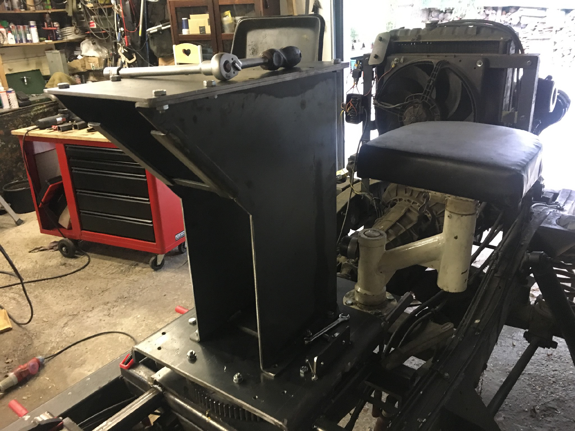
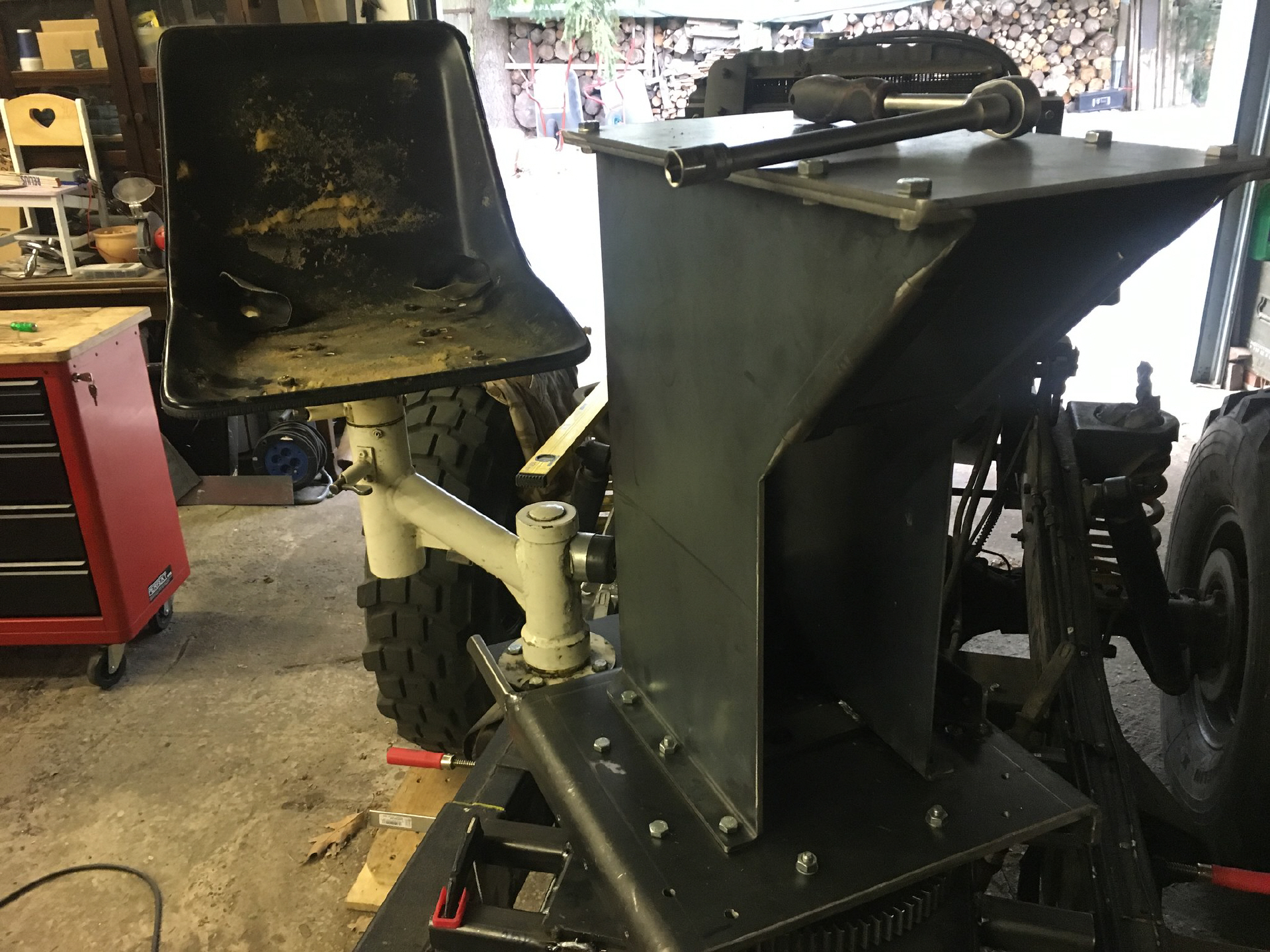
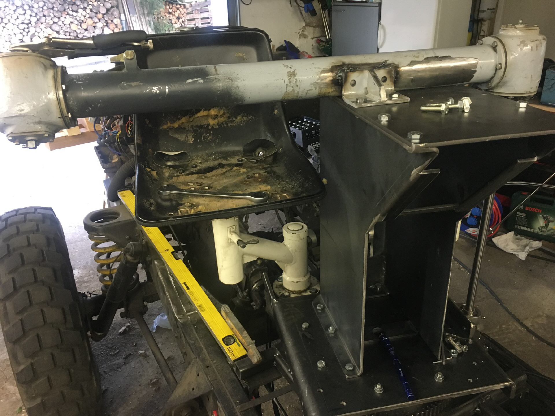
The rotary mount was tentatively mounted on the chassis for testing the rotary movement and to check measurements
To accommodate this whole unit 10mm thick plates are welded to the inside of the frame, are then bolted to the angle, which are welded to the base frame of the rotary mount. This effort I make only in this area, because a lot of weight comes together here
The angle gear I've discovered a long time ago on ebay. Former Bundeswehr (navy) part. Ratio 1: 1. The mount turns very easily, without effort.
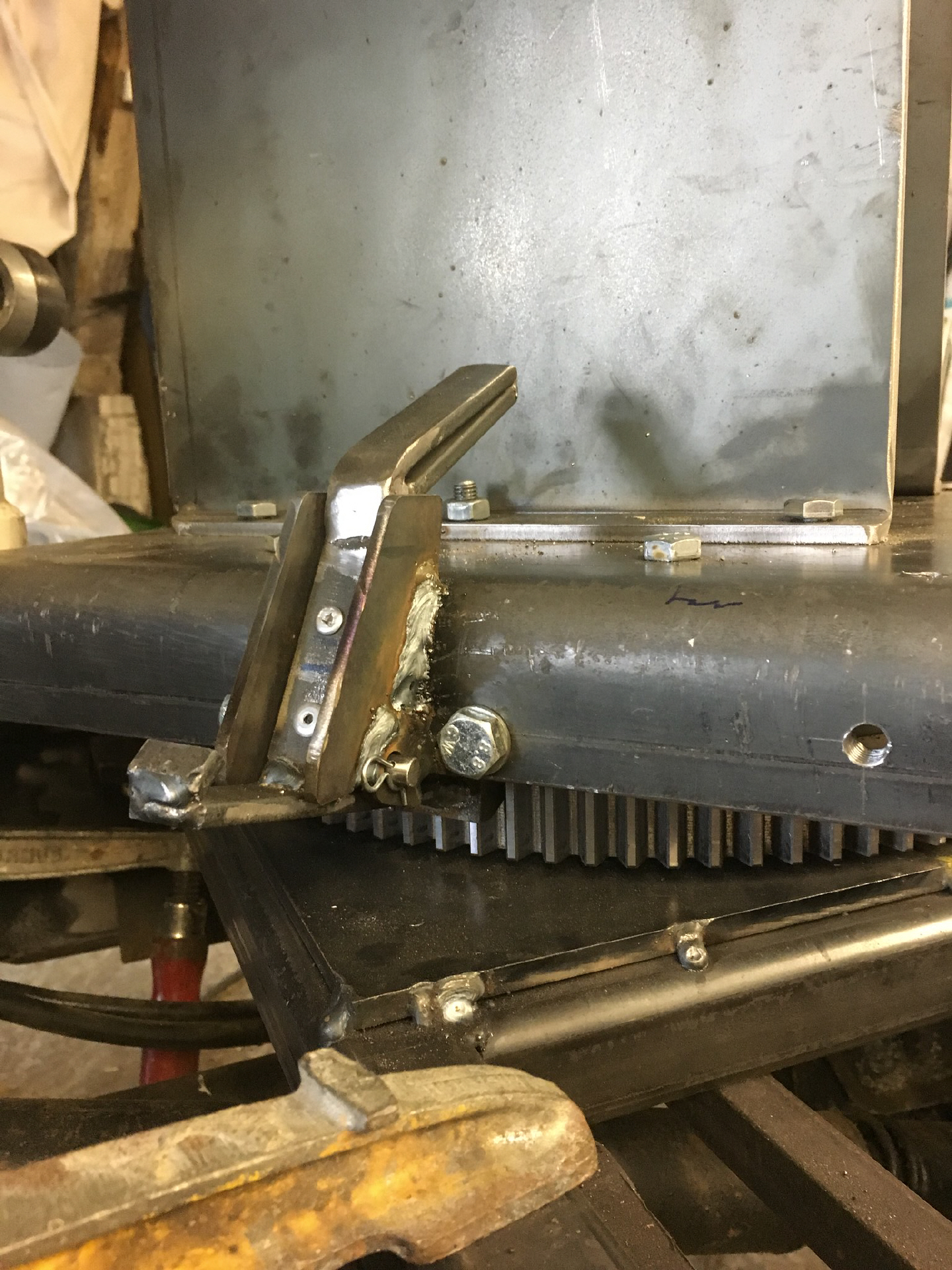
I have added an additional lock on the rotary mount. At the angle gear is also a (hinged) lock, but the turret so far only on 12,3,6, and 9 o'clock can be secured.
The additional lock secures in each turret position. Only when the lever is depressed, the turret can be turned. If you take your foot off the lever, a lock push into the gear and lock the turret.
The seats probably come from a M113.
The seat of the commander I have adapted according to the photos of the littlefield- 222.